
How Do Force Sensors Improve Robotic Weld Seam Tracking?
Force sensors improve robotic weld seam tracking by giving the controller feedback about physical contact with the workpiece. In a suitable contact-based system, a probe or compliant follower senses the joint, and the robot adjusts its path to keep that contact consistent. This can help compensate for part-position changes and some geometric variation that a fixed programmed path would miss.
The main condition is that the sensing tool must contact a feature that reliably identifies the seam. A force sensor does not directly see the weld joint, measure the weld pool, or guarantee penetration. Its usefulness depends on the joint geometry, mechanical arrangement, and how the controller turns force measurements into motion corrections.
How does force feedback help a robot follow a weld seam?
A programmed welding path assumes the joint will remain where it was taught. Actual parts can differ because of fixture clearance, forming variation, assembly tolerances, and distortion. Even when the robot repeats its motion accurately, the torch may miss the intended position if the workpiece has moved.
With contact-based seam tracking, a sensing element follows an accessible surface, edge, or groove. A force sensor measures the interaction between that element and the workpiece. Depending on the arrangement, the system may use a single force component or several force and torque components.
The controller compares the measured contact force with a target. If the follower presses harder against the reference surface, the controller can move away slightly; if contact weakens, it can move toward it. The direction of those corrections depends on the probe geometry and the selected control axes. Forward travel continues along the seam while the force loop adjusts permitted directions.
Maintaining contact is only useful when that contact has a known relationship to the joint. A probe riding on one flat surface may provide height information without revealing the lateral position of a nearby butt joint. A follower seated in a suitable groove can provide more positional guidance, provided it remains seated and does not bridge over irregularities.
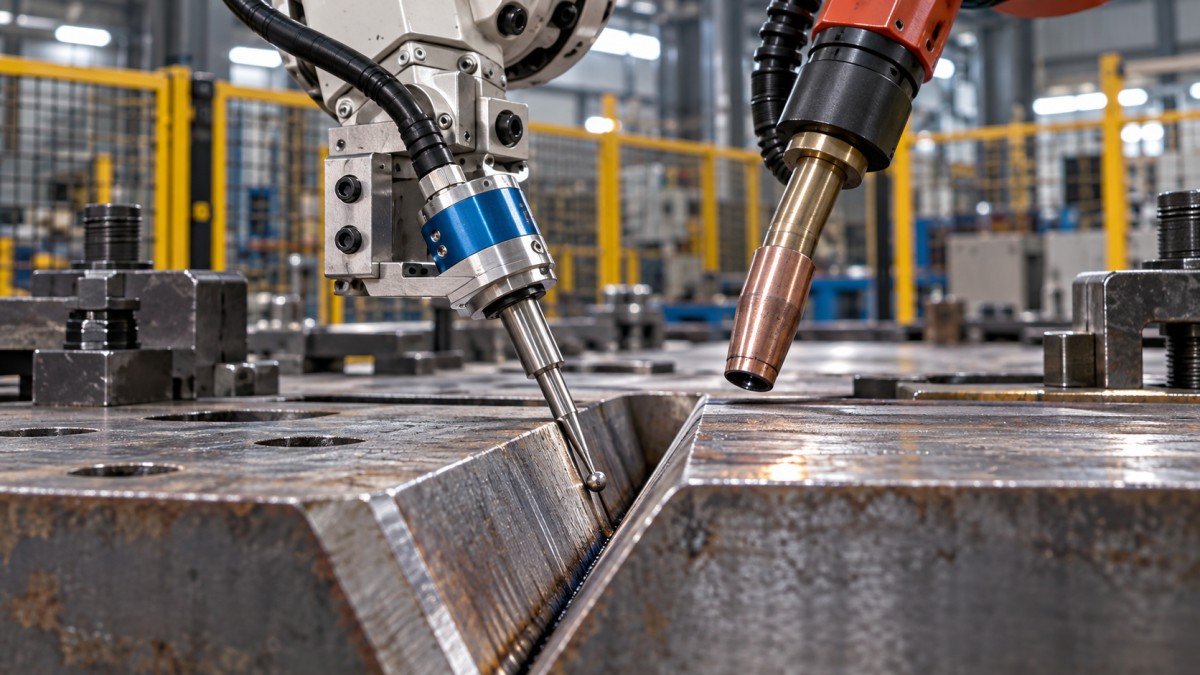
If the follower runs ahead of the torch, the controller must also account for their separation. A correction measured at the probe belongs to the location the torch will reach later. Applying it immediately at the torch can create tracking errors, particularly around curves and corners.
Does the welding torch need to touch the workpiece?
Usually, a dedicated probe or follower provides the mechanical contact in a force-assisted arc-welding arrangement. The torch remains positioned for the welding process. Deliberately pressing an arc-welding torch into the joint is not a general method of seam tracking.
A separate follower introduces practical constraints. It needs access to the reference feature without obstructing the torch, shielding gas, or robot motion. Its mounting must remain stable, and its offset from the torch must be calibrated. Tight corners, clamps, and short seams can make this arrangement difficult to use.
Force measurement also has different roles across welding processes. In resistance spot welding, electrode force helps establish the conditions for making a weld. That function is distinct from locating and following a continuous seam. A sensor specified for electrode force control should not automatically be treated as a seam-tracking solution.
Can force sensors correct fit-up errors and thermal distortion?
They can help correct where the robot travels, but they cannot automatically correct every change in how the joint must be welded.
Consider a fillet joint whose position shifts between assemblies. If a follower can reliably locate the joint, force feedback may help keep the torch aligned as the robot travels. If the joint also develops a larger gap, however, maintaining alignment does not by itself supply the additional filler metal or change the welding conditions needed to bridge that gap.
Gap variation may require separate measurement and a qualified strategy for adjusting travel speed, wire feed, or other process settings. A force signal alone generally cannot distinguish all relevant changes in joint geometry.
Thermal distortion creates a similar limitation. A follower can track movement at its own contact location. If welding heat moves the joint after the follower has passed but before the torch arrives, the stored correction may no longer describe the torch’s actual target. Probe placement, sensing delay, and the timing of distortion therefore affect the result.
Thin or flexible parts need particular care. Contact force can deflect the workpiece, causing the robot to follow geometry that the sensing tool itself has changed. The tracking force must be sufficient for stable measurement while remaining low enough to avoid unacceptable deformation or surface damage.
When is force-assisted seam tracking a practical choice?
It is most promising when the joint has a continuous, accessible reference feature, the workpiece tolerates contact, and the required corrections fit within the robot controller’s capabilities. The mechanical simplicity of following a well-defined feature can be valuable where optical access is difficult.
However, freedom from optical interference does not mean freedom from environmental problems. Spatter can alter the follower’s shape or make it stick. Scale, burrs, and tack welds can produce force changes that resemble a change in seam position. Heat can affect the sensing assembly, and moving cables can add loads to the measurement.
Contact tracking becomes less attractive when:
- The seam is flush and offers no reliable tactile feature.
- The material is easily marked or deflected.
- Fixtures block the follower’s path.
- Discontinuities repeatedly interrupt contact.
- The application needs detailed measurements of joint gap or cross-sectional shape.
For example, a pronounced groove may provide useful guidance, while a tightly fitted butt joint on a smooth sheet may offer little for a probe to follow. The same force sensor can be effective in one arrangement and provide insufficient information in the other.
How does force sensing compare with laser and through-arc tracking?
The useful comparison is the information each method can obtain from the actual joint. Sensor specifications alone do not establish which system will track it successfully.
Laser sensing is often a stronger candidate when joint profile or gap information is needed without physical contact. Its performance depends on viewing geometry, surface behavior, contamination, and protection from the welding environment.
Through-arc tracking can avoid a separate mechanical follower, but its usefulness depends on the welding process, joint shape, and tracking strategy. It should not be assumed to work on every joint simply because welding current is available.
Methods can also complement one another. A pre-weld search may establish the starting position, while another sensor handles changes during travel. Combining sensors is worthwhile when each supplies necessary information; otherwise, it can add calibration and maintenance effort without improving the result.
What makes a force sensor suitable for robotic welding?
Start with the force information the application needs. A single-axis sensor may be sufficient when the follower only needs to maintain contact in one known direction. A multi-axis force/torque sensor can provide more information when contact directions change or moments help identify abnormal loading. Extra measurement axes still require a control strategy that can use them.
Measurement range and usable sensitivity must be considered together. The sensor needs to tolerate expected loads and accidental contact, while still resolving the smaller force changes used for tracking. A high load rating alone says little about its ability to maintain gentle, consistent contact.
Sensor location affects what appears in the signal. A wrist-mounted sensor may measure tool weight, acceleration forces, cable drag, and contact loads together. Gravity compensation and coordinate transformations are needed to interpret those measurements as the robot changes orientation. A sensor closer to the follower can reduce some unwanted influences, but may face greater heat and spatter exposure.
The complete assembly also needs suitable stiffness, thermal protection, overload protection, and cable management. Electrical isolation and the welding return-current arrangement require attention so that unintended current paths do not damage components or disrupt measurements.
Controller compatibility can be the deciding factor. Reading force values into a supervisory system is different from using them for timely robot-path corrections. Confirm that the robot interface supports the required correction directions, update behavior, filtering, and fault responses.
Why can force-based tracking become unstable or inaccurate?
Instability often occurs when the controller reacts too aggressively to contact changes. A stiff follower, noisy signal, and delayed motion correction can produce repeated pushing and backing away. Increasing the force-control gain may amplify that behavior instead of improving accuracy.
Excessive filtering creates another problem: the signal becomes smoother but arrives too late to follow changing geometry. Tracking performance depends on the combined behavior of the sensor, mechanics, communications, and robot motion control.
Friction can also distort the measurement. A dragging probe may generate forces along the travel direction that vary with surface condition. If those forces enter the correction logic incorrectly, the robot can move away from the intended path. A suitable follower design and careful selection of controlled axes help separate useful contact information from unwanted loads.
Loss of contact needs an explicit response. The robot should not continue searching without limits when a follower leaves an edge or reaches an interruption. Correction boundaries, contact-loss detection, and defined stop or recovery behavior keep a local sensing problem from becoming a larger positioning error.
What should an application trial prove before installation?
A useful trial demonstrates that tracking works across expected production variation. One successful weld on a carefully aligned sample provides limited evidence.
- Define the variation. Include representative part offsets, joint shapes, tack welds, surface conditions, and fixture access.
- Check contact behavior. Establish whether the follower stays on the reference feature without marking, deflecting, or snagging the part.
- Verify torch position. Measure the resulting torch-to-joint relationship, including curves and starts or ends where probe offset matters.
- Evaluate weld quality separately. Confirm the weld meets the application’s acceptance requirements; stable contact force does not prove weld integrity.
- Test interruptions and maintenance. Assess contact loss, contamination, follower wear, replacement, and recalibration.
Track total production effort as well as weld results. A system may reduce path touch-up but introduce cleaning or access delays. The practical benefit depends on whether it reduces the combined burden of adjustment, inspection, rework, and maintenance.
Can an existing welding robot be upgraded with force tracking?
Often it can, provided the controller supports the necessary external feedback and motion correction. Available payload, tool clearance, communications, and access to suitable software functions all affect feasibility. Adding a sensor mechanically may be straightforward while integrating a stable tracking loop is much more demanding.
Does a force sensor make the welding cell safe for human contact?
No. A process force sensor does not automatically provide a safety-rated protective function. Welding also introduces heat, arc radiation, fumes, and other hazards. Changes to tooling or robot behavior need to be considered within the cell’s safeguarding and risk assessment.
Will force feedback eliminate robot teaching?
It can reduce repeated path adjustments, but the robot still needs a nominal route, torch orientation, welding parameters, and bounded correction rules. The most useful starting question is whether the proposed contact feature consistently reveals the seam position. Once that is demonstrated, sensor selection and controller integration have a clear purpose.
Search News
Hot Articles
- API 682 & REACH ComplianceEdge Computing for Robotics: How On-Site Processing Reduces LatencyNov 04, 2026
- API 682 & REACH ComplianceCobot Safety Standards: ISO Requirements for Risk Assessment and IntegrationNov 03, 2026
- API 682 & REACH ComplianceSmart Logistics Automation: How to Plan a Warehouse RolloutNov 02, 2026
Popular Tags
Need ExpertConsultation?
Connect with our specialized leisureengineering team for procurementstrategies.
Recommended News