
Why Does an AI Weld Inspection Model Miss Some Defects?
Why Does an AI Weld Inspection Model Miss Some Defects?
Why does an AI inspection model miss some welding defects? Usually, the failure falls into one of three categories: the sensor never captured usable evidence, the model did not recognize the evidence, or the inspection system failed to turn a detection into the correct production decision. Those are different problems, and retraining the model will not fix all of them.
For manufacturers using automated weld inspection, the consequences can include rework, escaped nonconforming parts, or downstream failures. Yet “the AI missed it” is often too broad a diagnosis. A crack hidden by glare, internal porosity beyond a camera’s view, and a correctly detected indication filtered out by software require entirely different responses.
The useful starting point is not overall accuracy. It is whether the complete inspection chain can reliably find the particular discontinuities that matter on the actual joint.
Can the inspection sensor actually see the defect?
A conventional surface camera records reflected light. It can reveal visible cracks, surface-breaking pores, undercut, and bead appearance when resolution, contrast, and viewing angle are adequate. It cannot directly establish that a weld is free of internal porosity, buried lack of fusion, or inaccessible root imperfections.
That distinction matters when reviewing demonstrations. A model may associate certain surface patterns with internal problems in a particular dataset. Such a correlation is not the same as directly measuring internal integrity, and it may fail when the material, welding procedure, or joint geometry changes.
Consider a fillet weld inspected from above. The bead face may look consistent while the joint root remains hidden. Adding more images from the same viewpoint does not remove that blind spot. A second view may improve surface coverage; a different inspection method may be needed for subsurface evaluation.
Laser profiling and other 3D sensing methods can help measure bead shape, position, and accessible surface geometry. They do not automatically establish penetration or fusion quality. Ultrasonic testing, radiography, penetrant testing, or magnetic particle testing may provide complementary evidence, depending on the material, discontinuity, geometry, and applicable procedure. No single method is suitable for every weld.
Before evaluating an AI model, define the inspection scope: which surfaces are covered, which discontinuities are targeted, what dimensions matter, and what remains outside the method’s capability.
Why does a visible crack disappear in the production image?
Welds are difficult optical targets. Curved metallic surfaces create bright reflections beside deep shadows. Oxidation, spatter, soot, and changing surface finish alter the appearance of otherwise similar joints. A hairline crack that is obvious under a handheld light may have almost no contrast under the installed illumination.
Resolution also needs to be considered at the workpiece, not just on the camera specification sheet. A large field of view spreads the available pixels across more material. If the smallest relevant indication occupies too few pixels, its appearance becomes unstable. Motion blur, poor focus, and image compression can remove the remaining evidence.
There is no universal pixel count that guarantees detection. Crack width, orientation, optical contrast, lens performance, and the processing method all matter. The practical test is whether representative indications remain distinguishable in saved production images—not whether they appear visible in a magnified laboratory photograph.
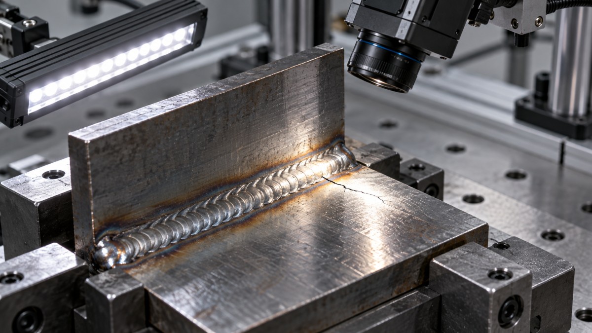
A useful diagnostic exercise is to capture the same suspect weld under the production setup and under controlled alternative lighting and viewing angles. If the indication becomes clear only after changing illumination, address image acquisition before collecting thousands of additional training samples. Directional lighting, multiple exposures, or photometric stereo may help in suitable applications, but each must be checked against line speed and surface variability.
How can a model perform well in testing and still miss production defects?
The training data may describe the demonstration cell better than the production process. Images from one material batch, one robot program, and one lighting setup can produce convincing validation results while leaving major gaps in real-world coverage.
Rare defects are particularly difficult. A dataset can contain many acceptable welds but only a narrow selection of cracks or incomplete welds. The model then learns those examples, not every physical form the defect can take. A short crack near a weld toe may look quite different from a longer crack crossing the bead.
Dataset splitting can also create misleading confidence. If adjacent frames from the same weld appear in both training and test sets, the test is not genuinely independent. Separating data by part, production run, or another meaningful source of variation provides a more demanding assessment.
Labels deserve equal scrutiny. Is a dark line a crack, a scratch, or a shadow? Is a geometric irregularity rejectable under the applicable acceptance criteria, or merely unusual? Where practical, qualified inspection personnel should resolve ambiguous examples using suitable supporting examinations. Otherwise, the model may learn inconsistent decisions.
Synthetic defects and image augmentation can supplement scarce data. They should not replace independent testing on representative physical defects: a digitally drawn line does not necessarily reproduce the optical behavior of a real crack.
Can detection thresholds hide defects the model has noticed?
Yes. Many systems produce candidate detections with confidence scores, then apply thresholds and filtering rules. A weak indication may be discarded because its score is too low, its detected area is too small, or it falls outside the configured inspection region.
This creates a familiar production trade-off. Lowering the threshold may recover more true defects but increase false rejects caused by spatter, reflections, or harmless surface marks. Raising it can reduce nuisance alarms while allowing more defects through. Confidence scores should not automatically be interpreted as calibrated probabilities of weld failure.
Threshold selection therefore belongs in the quality decision, not just the software setup. Review performance by defect type and relevant size range. A threshold that works well for missing weld segments may be unsuitable for fine cracks. An uncertain result can also trigger review or secondary inspection rather than being forced into an immediate pass decision.
What can go wrong after the camera and model work correctly?
An inspection station is a synchronized system: robot motion, lighting, camera triggering, inference, part tracking, and reject handling must agree. A correct detection attached to the wrong serial number is still an inspection failure.
In a robotic cell, fixture variation can move the weld outside a tightly cropped region of interest. A changed robot path can alter camera distance or leave part of the seam unobserved. At higher throughput, an inference queue may delay a decision beyond the reject station’s timing window.
Check these integration points during troubleshooting:
- Does every required weld segment have a confirmed image, rather than merely a trigger command?
- Is the correct inspection recipe linked to the part variant and robot program?
- Are dropped frames, timeouts, and unavailable cameras explicitly handled?
- Can the team trace the image, model version, decision, and reject confirmation to the same part?
A missing image must not silently become a pass. The appropriate response—hold, review, reinspection, or another controlled action—should be defined in the production quality plan.
Which performance measures reveal the real risk?
Overall accuracy can conceal poor defect detection when acceptable welds dominate the dataset. A system that passes almost everything may appear successful while contributing little protection against rare defects.
Defect recall measures how many reference-positive defects the system detects. Precision indicates how many reported detections correspond to actual defects. Both matter, but neither is sufficient without knowing the inspection unit and reference method. An image-level result is not equivalent to a weld-level or part-level result.
Ask for results broken down by defect category, relevant dimensions, joint type, and production condition. Include false rejects because excessive nuisance alarms can overload review staff and encourage workarounds. Keep missed defects separate from uninspected regions and unavailable results; combining them hides different corrective actions.
A test containing very few relevant defects cannot establish reliable performance for that defect population. Validation should document sample limitations and uncertainty rather than turning a small successful trial into a broad capability claim.
When should the team retrain, change sensors, or add another inspection method?
Follow the evidence. If qualified reviewers cannot reliably identify the target indication in the captured images, improve the optical setup or reconsider the sensing method. If the indication is clear but consistently misclassified, investigate training coverage, labels, and model settings. If detections appear in software but defective parts pass downstream, inspect decision logic and handling integration.
For equipment comparisons covered by Global Industrial Robotics & Smart Equipment (IRSE), this distinction is more useful than a generic “AI-powered” claim. Buyers need to understand the relationship between sensing capability, robot-cell integration, inspection coverage, and quality requirements—not just inference speed.
After corrective changes, validate on independent parts under representative operating conditions. Preserve challenging examples, monitor performance after material or process changes, and control model versions. Adding data is not evidence of improvement until the revised system is tested.
For the next missed defect, retain the part, raw image, capture settings, inspection recipe, model output, and final disposition. Establish where the evidence disappeared before changing the algorithm. That investigation determines whether the right investment is better lighting, better data, corrected integration, or an inspection method that can reach what the camera cannot see.
Search News
Hot Articles
Popular Tags
Need ExpertConsultation?
Connect with our specialized leisureengineering team for procurementstrategies.
Recommended News