
Are LiDAR Sensors Reliable Around Welding Smoke and Reflections?
LiDAR sensors can work reliably near welding operations when their optical paths remain sufficiently clear and the installation accounts for reflective surfaces. Reliability becomes harder to maintain when a sensor must look through dense, changing welding fumes or detect polished metal at unfavorable angles. A sensor that navigates successfully beside an enclosed welding cell may struggle when the same cell opens and releases a plume across its scanning plane.
For AMRs, AGVs, and welding automation, the decision therefore depends on the task: maintaining localization, detecting an obstacle, measuring a component, or supporting a protective stop. Each has different consequences when returns become intermittent. A successful demonstration in a clean aisle does not establish suitability beside an operating welding process. The installation needs to be evaluated with welding active, extraction running, representative parts present, and the robot following its intended routes.
What does welding smoke do to LiDAR measurements?
Welding fumes contain airborne particles that can scatter the laser light traveling between a LiDAR sensor and its target. Some light returns from the plume itself, while less reaches the intended surface and returns to the receiver. Depending on particle concentration, path length, sensor design, and processing settings, the result can be apparent obstacles within the plume, missing measurements behind it, or fluctuating distance readings.
The effect is not simply “smoke present” versus “smoke absent.” A thin plume crossing a short measurement path may have little operational impact. A concentrated plume that fills the sensor’s view can obscure several useful features simultaneously. Changing airflow can move the plume into and out of the scanning plane, producing faults that are difficult to reproduce during a brief commissioning check.
This matters differently for different functions. A navigation system may tolerate losing some points if enough stable walls, columns, and other features remain visible. An obstacle detector can become unusable if plume returns repeatedly trigger stops. A dimensional inspection task may fail because scattered or missing returns compromise the required surface coverage, even while navigation remains stable.
Smoke also creates a maintenance problem separate from airborne interference. Deposits on the optical window can reduce transmitted and received light after the surrounding air has cleared. Welding spatter can damage an exposed window. These conditions require separate attention because software settings that help reject airborne returns cannot restore a contaminated or damaged optical surface.
Why do shiny metal surfaces cause missing or misleading returns?
A smooth metal surface can reflect much of the incident laser light away from the receiver. Whether the sensor receives a usable return depends on the surface finish, angle, distance, wavelength, and receiver geometry. A polished panel that is visible from one approach may produce a sparse or missing return from another. Curved and cylindrical parts introduce additional variation as the robot moves.
Other geometries can produce strong returns or indirect reflections. Light may travel along an unintended path before reaching the receiver, creating a measurement that does not correspond to the direct distance to the visible surface. Receiver behavior under very strong illumination also varies between sensors. These effects should be investigated in the actual installation rather than treated as a universal property of all metal objects.
The practical concern is an unstable representation of the workspace. A reflective fixture may disappear from portions of a point cloud, while a nearby surface appears displaced or generates inconsistent points. Navigation software can sometimes reject isolated outliers, but repeated gaps can remove useful localization features or leave an obstacle poorly represented.
Reflective tape and polished metal are not interchangeable test targets. Retroreflective materials return light toward its source, while a mirrorlike surface directs light according to its orientation. Performance around reflective markers does not establish dependable detection of stainless steel sheet, aluminum housings, or polished tooling.
Welding arc light adds another possible source of interference. Its effect depends on spectral overlap, optical filtering, receiver design, exposure geometry, and the sensor’s interference handling. A wavelength specification alone does not establish immunity to either arc light or welding fumes.
Which installation changes make the biggest difference?
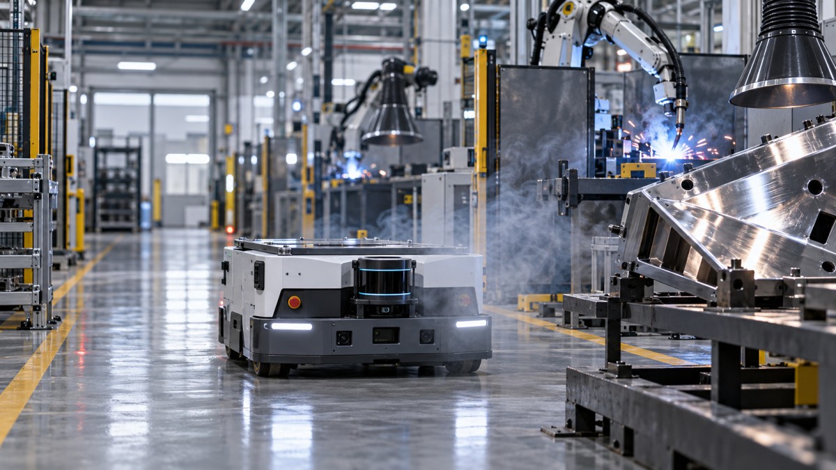
Start by reducing how often the measurement path intersects the plume. Effective fume extraction, suitable cell enclosure, and route placement can improve sensing conditions while also serving the welding process. Where practical, position an AMR route outside the area where fumes escape when doors open or parts transfer. Check the airflow under production conditions: an open access door or a repositioned extraction hood can change where the plume travels.
Sensor height and orientation deserve particular attention. Raising a navigation scanner may provide a clearer view above some obstructions, but could place it directly in rising fumes. Lowering it may avoid that plume while exposing it to low fixtures, debris, or different reflective surfaces. A change that improves localization can also change obstacle coverage. Evaluate both functions before accepting the mounting position.
For reflective targets, changing the viewing geometry can help, although no single mounting angle guarantees success across all parts. Where the application permits, stable matte landmarks can provide additional localization references away from polished equipment. Keep those references visible through normal vehicle movement, part staging, and cell access.
Physical protection also needs optical consideration. A hood or replaceable protective window may reduce exposure to spatter, but an unsuitable cover can attenuate the beam, introduce reflections, or restrict the field of view. Use arrangements supported by the sensor manufacturer and include them in testing. An air purge may help keep a window clean, provided it does not disrupt shielding gas, fume capture, or other process requirements.
Software filtering should follow these physical improvements. Aggressive rejection of weak or isolated returns may reduce nuisance detections, but it can also remove legitimate measurements from small, dark, distant, or poorly oriented objects. Assess filtering against the objects the system must detect, including those that already produce marginal returns.
Does a different LiDAR technology solve the problem?
Sensor architecture matters, but broad labels such as “industrial,” “solid-state,” or “3D” do not establish performance in a welding environment. Useful questions concern how a specific sensor behaves when the direct return is weak, when particles generate additional returns, when the receiver sees intense background light, and when its optical window becomes contaminated.
A 3D LiDAR can provide observations outside a single horizontal plane, potentially retaining useful features when a localized plume obscures part of the view. That advantage depends on the scene and integration. A plume filling the relevant field of view can still degrade the data, and increased point density cannot recover a surface whose return never reaches the receiver.
Some sensors provide multiple returns, signal intensity, confidence values, or contamination diagnostics. These outputs can help an integrator identify degraded conditions or distinguish likely plume returns from persistent surfaces. Their value depends on how the downstream software uses them. Ask what happens when measurements are rejected: does the system reduce speed, stop, report degraded localization, or continue using older information?
Complementary sensing may improve availability. Wheel odometry and inertial measurements can support navigation during brief losses of environmental features, although uncertainty grows without reliable correction. Radar may offer useful detection in conditions that impair optical sensing, but its coverage, resolution, and integration requirements differ. Cameras also need evaluation against fumes, glare, and arc light. Any proposed combination needs a defined response when its sensors disagree.
How should a factory validate reliability before buying?
Define acceptable behavior before comparing sensors. “Works near welding” is too vague to support an acceptance decision. For a logistics robot, the relevant outcomes may include route completion, localization stability, nuisance stops, and recovery time. For measurement, they may include accuracy, repeatability, and valid surface coverage. For protective detection, the assessment must address the required safety function.
A useful trial should include the following operating conditions:
- Normal welding cycles: Test with representative welding parameters, extraction settings, fixtures, and production parts.
- Plume movement: Include door opening, part transfer, and foreseeable airflow changes that move fumes across the sensing path.
- Reflective geometry: Approach shiny panels, curved components, tooling, and fixtures from the routes and angles the vehicle will actually use.
- Combined challenges: Test reflective targets with welding active, since separate clean-air and smoke tests can miss interacting effects.
- Window condition: Evaluate performance over a realistic maintenance interval, within the manufacturer’s permitted operating conditions.
- Fault recovery: Check behavior when visibility deteriorates, when localization confidence falls, and when normal visibility returns.
Record sensor measurements alongside robot behavior. A point cloud that looks clean after filtering may conceal extensive rejected data. Conversely, a noisy raw point cloud may still support stable navigation if sufficient dependable features remain. Useful evidence links the data to the task: where localization changed, which object was missed, what triggered a stop, and how the system recovered.
Avoid judging reliability by average performance alone. Intermittent faults at one cell exit can dominate operational disruption even when the rest of a route works well. Repeat the challenging approaches across relevant production states, and retain the mounting details, settings, software versions, and environmental conditions so the accepted configuration can be reproduced.
Can the same LiDAR provide navigation and personnel protection?
Some installations use separate devices for navigation and protective detection; others use equipment designed to support particular safety functions. The distinction must remain explicit. Successful mapping or obstacle avoidance does not establish that a sensor is suitable for personnel protection. Safety capability depends on the device, its approved configuration, the control system, and validation of the complete installation.
For protective use, review the manufacturer’s operating limits concerning contamination, ambient light, target characteristics, and environmental interference. The application assessment should also account for detection coverage, response time, vehicle stopping behavior, and what happens when the scanner reports a fault or reduced visibility.
Repeated protective stops near a welding plume indicate a condition that needs investigation. Changing field geometry or filtering solely to improve throughput can affect coverage and must be assessed accordingly. The supplier should explain how the proposed configuration maintains the required protective function under the expected conditions.
A defensible purchasing decision rests on a specific operating envelope: where the sensor is mounted, which routes and surfaces it must observe, how fumes are controlled, how the window is maintained, and what the machine does when sensing degrades. If a supplier can demonstrate those conditions and document the resulting behavior, LiDAR can be a practical choice near welding. If dependable operation requires an unobstructed view that the process cannot maintain, changing the route, enclosure, or sensing arrangement should come before committing to the installation.
Search News
Hot Articles
- OTR Radial TiresUS Announces Overhaul of Federal Tire Safety StandardsOct 31, 2026
- API 682 & REACH ComplianceRobot Compliance Standards: Which Safety Standards Apply to Industrial Robots?Oct 31, 2026
- Sealing TCO & OTR CapitalUS Revises Section 338 Tariffs on Canada, Sets 15% Rate for Rubber and Plastic MoldsOct 30, 2026
Popular Tags
Need ExpertConsultation?
Connect with our specialized leisureengineering team for procurementstrategies.
Recommended News