Why Do Vacuum Grippers Drop Oily Metal Parts?
Why Do Vacuum Grippers Drop Oily Metal Parts?
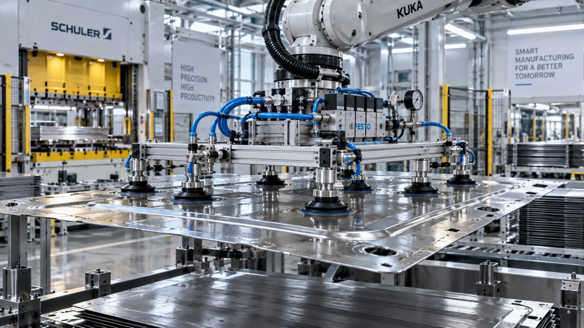
What causes vacuum grippers to drop oily metal parts? The short answer is that oil makes it harder to create and maintain a stable pressure difference between the suction cup and the workpiece. The operational answer is more complicated. A robot may pick a stamped panel reliably for several cycles, then lose it during acceleration, rotation, or a slight change in part position. The cup is often blamed first, but the failure can come from a combination of surface film, leakage, cup deformation, vacuum supply limits, part geometry, robot motion, and maintenance conditions.
This issue is common in press tending, CNC machine loading, body-in-white handling, coil-processing lines, and transfer stations handling metal sheets, blanks, castings, and machined components. Lubricants, corrosion inhibitors, coolants, and drawing oils are necessary process materials in many of these environments. They also turn a seemingly simple end-of-arm tooling decision into a system-level reliability question.
A vacuum gripper does not need a perfectly dry surface to work. It does, however, need enough effective sealing area, sufficient available vacuum flow, and enough holding margin to resist the real forces generated by the robot and process. When one of those conditions disappears, dropped-part risk rises quickly.
Oil Changes the Seal Before It Changes the Holding Force
Vacuum holding force is commonly approximated as pressure differential multiplied by effective suction area. That relationship is useful, but it can be misleading in oily applications because the theoretical cup area is rarely the effective sealing area. The cup must conform to the surface and limit air entry around its lip. Oil can interfere with that contact in several ways.
A thin, uniform oil film may allow a cup to seal reasonably well under static conditions. A heavier film, pooled lubricant, machining coolant, or residue mixed with chips can create micro-channels at the sealing edge. Air leaks into the cup faster than the vacuum source can evacuate it. The vacuum switch may still report an acceptable level at pickup, yet the pressure reserve may be too small to survive a rapid move.
Oil also reduces friction. This matters because vacuum cups do not only support a part vertically; they may need to resist shear forces as the robot accelerates, brakes, or changes orientation. A flat steel blank can slide relative to a cup even when the cup has not fully lost vacuum. During a high-speed transfer, that sliding can distort the lip, open a leak path, and cause the part to detach. In other words, a gripper may have enough nominal lifting force but insufficient resistance to lateral movement.
Surface condition is rarely consistent across a production line. One blank may carry a light protective film, while another has oil concentrated near an edge after stacking. CNC parts can arrive with coolant trapped in recesses. A design validated on clean samples may therefore look stable during commissioning and become unpredictable in production.
The Cup Material May Be Incompatible with the Process Fluid
Not every elastomer behaves the same way around industrial oils. Cup material affects flexibility, sealing behavior, wear, temperature tolerance, and chemical compatibility. Some materials soften, swell, harden, or lose elasticity after repeated exposure to certain lubricants, coolants, or cleaning chemicals. The result may be subtle at first: slower vacuum buildup, more frequent cup marks, uneven lip wear, or a drop in repeatability at one station.
Material selection should therefore start with the actual fluid, not merely the phrase “oily metal.” Teams should identify whether the contamination is stamping oil, soluble coolant, neat cutting oil, rust preventive, release agent, or a mixture. Its temperature, concentration, replenishment cycle, and contact time can all affect cup life. A supplier’s compatibility guidance is useful, but it should be verified against the fluid used on the line rather than against a generic oil category.
Cup geometry matters alongside material. Bellows cups can compensate for height variation and uneven pickup, but they may be less stable under some lateral loads. Flat cups can provide a broad contact face on smooth sheet material, while deep or specially profiled cups may be better suited to formed panels, ribs, and shallow recesses. There is no universally superior cup shape; the correct choice depends on the leakage risk and the directions of force during the robot path.
A Vacuum Reading Is Not Proof of a Secure Pick
A common troubleshooting mistake is to ask only whether the system reaches the set vacuum level. That check is necessary, but it does not describe the entire handling event. A cup can reach a target vacuum in a stationary position and still fail once the arm rotates, the blank flexes, or one cup encounters an oily patch.
The vacuum source must provide both adequate vacuum level and enough flow capacity to compensate for expected leakage. These are related but different properties. A high vacuum level with limited flow can be vulnerable when a cup seals imperfectly. A vacuum generator or pump with higher flow may recover more effectively from small leaks, although the overall design still needs proper piping, valve sizing, filters, and control logic.
Long hoses, undersized fittings, clogged filters, cracked tubing, and poorly maintained valves all consume performance margin. In a multi-cup tool, one leaking cup can affect the whole circuit if zones are not isolated appropriately. Check valves, individual vacuum sensing, and segmented circuits can prevent one poor contact point from turning into a complete pick failure. Their value depends on the part family and the consequences of a dropped part; they are not a substitute for a sound mechanical layout.
For critical transfers, it is often more useful to monitor how quickly vacuum is achieved and how it changes during motion than to rely on one pickup threshold alone. Trend data can reveal gradual cup wear, contamination buildup, or changes in oil application before the line reaches a failure point.
Part Geometry and Robot Dynamics Often Expose the Weak Point
Metal parts are rarely ideal vacuum targets. Stamped blanks may have burrs, holes, curvature, embossed features, draw beads, or local oil pooling. Perforated sheet creates continuous leakage paths unless the cup position avoids openings. Thin blanks can flex when lifted, reducing contact at some cups and shifting load unexpectedly to others. A cast or machined part may offer only narrow, interrupted, or rough surfaces for sealing.
The location of each cup should be assessed against the part’s center of gravity, stiffness, and likely orientation during travel. Placing cups symmetrically on a CAD model is not enough if the real part sags, arrives slightly skewed, or contains oily areas that vary between batches. In practice, pickup validation should include actual production material, realistic lubricant condition, and the intended range of stack height or fixture variation.
Robot motion can turn a marginal grip into a dropped-part event. Fast acceleration generates inertial loads. Sharp path changes introduce lateral forces. Sudden braking can cause a thin panel to swing or peel away from an outer cup. The tool may be capable of lifting the part slowly but not capable of carrying it through the programmed cycle at full speed.
Reducing speed is a valid diagnostic step, but it should not automatically become the permanent fix. If a minor acceleration reduction eliminates failures, the result points to inadequate safety margin in the gripper layout, vacuum reserve, or cup-to-part friction. The final decision should weigh throughput requirements against a redesign that gives the cell a more robust operating window.
Where the Failure Happens Tells You What to Investigate
Do Not Treat Every Oily-Part Problem as a Vacuum Problem
Vacuum is often an effective handling method for oily sheet metal, but it is not automatically the right method for every part. If the available sealing surface is too limited, the part is highly porous or perforated, oil coverage is extreme, or a dropped component would create an unacceptable safety or quality risk, alternative or hybrid EOAT should be considered.
Mechanical locating features, edge supports, clamps, magnetic gripping for suitable ferrous materials, or a combined vacuum-and-mechanical retention design can add security. Each option introduces its own constraints. Magnets may complicate part separation and may not suit all materials or surface requirements. Mechanical grippers need accessible features and can interfere with tooling. Hybrid designs add weight and control complexity. The question is not which technology sounds stronger; it is which one tolerates the real production variation without damaging the part or slowing the cell beyond its takt-time target.
A useful engineering review also distinguishes between a single dropped part and a hazardous release. Parts transferred above personnel, moving equipment, or sensitive fixtures require a broader risk assessment. Robot safety requirements, guarding, emergency behavior, retained-energy considerations, and local machine safety obligations should be reviewed as part of the cell design. Vacuum monitoring contributes to risk reduction, but it does not independently establish that a handling system is safe.
A Better Validation Method for EOAT Selection
The strongest solution usually emerges from testing the full handling condition rather than comparing suction cup catalog ratings. Start with representative parts that reflect the actual range of thickness, flatness, surface finish, and oil condition. Include the worst credible pickup position, not just the easiest central location. Then test the intended robot path, acceleration, orientation changes, and release sequence.
During evaluation, document more than pass or fail. Record cup placement, vacuum buildup behavior, leakage symptoms, part movement, maintenance access, and the effect of production fluid. If machine vision or 3D sensing is already used in the workcell, it may also help identify shifted blanks, warped parts, double-sheet conditions, or position deviations before the robot commits to a pickup. Vision cannot repair a weak seal, but it can reduce failures caused by picking the wrong surface or contact zone.
This is the kind of cross-disciplinary decision that sits between robot programming, pneumatic design, material handling, machine vision, and factory operations. For integrators and factory teams, a practical review should include the robot payload and path, vacuum architecture, cup material compatibility, part variability, cleaning practices, and recovery logic after a failed pick. Procurement teams should ask suppliers to explain the assumptions behind proposed holding capacity and maintenance intervals rather than accepting a nominal force figure in isolation.
IRSE’s coverage of end-of-arm tooling, robotic workcells, vision systems, and flexible manufacturing focuses on these connected decisions. The useful question is not simply whether a vacuum gripper can lift an oily metal part. It is whether the complete gripping system can keep hold of that part across the oil conditions, motion profile, production variation, and maintenance reality of the line.
Before changing cups or increasing vacuum capacity, inspect the failed parts, map the failure point in the robot cycle, and confirm what has changed in the process fluid or pneumatic circuit. That evidence usually reveals whether the right next step is a different cup, better circuit segmentation, revised tool geometry, a calmer trajectory, or a move away from vacuum-only handling.
Search News
Hot Articles
- OTR Radial TiresUS Announces Overhaul of Federal Tire Safety StandardsOct 31, 2026
- API 682 & REACH ComplianceRobot Compliance Standards: Which Safety Standards Apply to Industrial Robots?Oct 31, 2026
- Sealing TCO & OTR CapitalUS Revises Section 338 Tariffs on Canada, Sets 15% Rate for Rubber and Plastic MoldsOct 30, 2026
Popular Tags
Need ExpertConsultation?
Connect with our specialized leisureengineering team for procurementstrategies.
Recommended News